NEW ELECTRIC BIKE PROJECT 2016
DESIGN AND IMPLEMENTATION OF A novel power scrambler FOR IMPROVING
FUEL EFFICIENCY.
Abstract
To meet the challenges
of constantly rising fuel supplies, a new power scrambler with high efficiency
is designed by increasing the kilometre range. In all kind of bikes, mechanical
energy is produced in the front wheel during roving. In this paper, a technique
is proposed to utilize the mechanical energy by using an alternator for
conversion. Alternator is placed in the front wheel of power scrambler which
converts the mechanical energy into electrical energy. Various power
electronics circuits are intended, to utilize the produced energy for charging
the battery in the power scrambler. This helps in increase the efficiency of
the power scrambler. For instance if 10:1:5 is the kilometre ratio of the
electric bike, with the use of the alternator, the kilometre will be decreased
by the ratio 10:1. But subsequent to its connection to the charging system, the
kilometre is increased by the ratio 10:5. The main objective of this paper is
to increase the usage of the electric bike, since this will reduce the usage of
the extinct fuels.
Keywords:
Power
scrambler (electric bike), BLDC motor, DC-DC boost converter, Lead-acid
battery.
INTRODUCTION


BLOCK
DIAGRAM OF OUR PROJECT
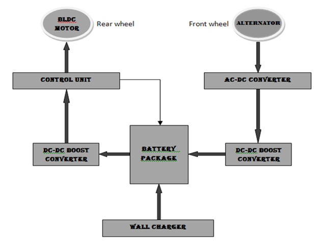

In this block
diagram, there are two blocks one is the existing system, which is already in
the e-bike and another one is the new system, which we are implementing in the
new power scrambler. In the existing system, battery is charged by using the
wall-charger. Then the control unit is provided to control the overcharging of
the battery and to separate the supply for head light and indicator light and
also used to convert the DC to 3 phase AC for providing supply to the BLDC
motor in the back wheel of e-bike. In our project, we are placing the
alternator in the front wheel, it will convert the mechanical energy into
electrical energy.
PROJECT
DESINGNING REQUIREMENTS
CIRCUIT
DIAGRAM
 This is the DC-DC boost converter circuit used in our project, for boosting up the output voltage of the alternator. We are getting the 12 voltage output from the alternator. This voltage is not sufficient for charging the batterybecause the charging voltage of the battery is 48v. So the circuit is used in our project.


ALTERNATOR


In the front wheel of the e-bike, BLDC
motor was used as an alternator in this project. Because the motor was used in
all type of e-bikes in the back wheel. The field of an alternator is permanent
magnet. So it does not need supply but it will produce emf(electro motive
force) and also the motor will be compact in size for placing in front wheel.
PROJECT
DESCRIPTION
In all kind of bikes, mechanical energy
is produced in the front wheel during the travelling time but it is not
utilised. In our project, we are placing the alternator in the front wheel. An alternator
will convert mechanical energy in to electrical energy. From that alternator,
we are obtaining the output voltage varying from 0-30v. for our convenience, we
are making the voltage constant of 12v by using the zener diode. But the 12v is
not sufficient to charge the battery. So, we are using the DC-DC boost
converter circuit for boosting up the voltage up to 48v for charging the
battery.
GRAPH
BATTERY
We are using the 48v sealed lead acid
battery. Here, it will be separated in to four 12v batteries because for our
size of convenience. Then the four 12v batteries are connected in series.
CONCLUSION
We are already having the high speed and high
load capacity electric bike in the market. E-bike is the pollution free bike
but it is not efficiently used due to many reasons. One of the main reason is
the lack of kilometre range. So we are improving its efficiency. In near
future, fuel may become extinct. So the fuel bikes are not used. At that time
an alter method will be needed, so this will be helpful at that time.
REFERENCES
1.Yoshihiro Nakazawa, Chiaki Humagai, Mikio Kato.
“Development of an electric scooter for practical
use” in JSAE
Review 15 (1994) 373-377
2. Chien-Tung Liu, Bing-Ming Lin, Jyh-Sheng Pan.
“Design and development of a zero-emission scooter
for Taiwan” in Journal of Power Sources 59
(1996) 185-187
3. Peter A. Lehman, Charles E. Chamberlin. “Design
and Performance of SERC’s Fuel Cell Powered
Vehicle
Fleet” in Fuel Cell Seminar Abstracts
1998. 714-717
4. H. Yamamura, R. Masaki, O. Koizumi, K. Naoi and
S. Naito,
“Development of powertrain system for Nissan FEV”,
in
Proceedings of the 11th Electric Vehicle Symposium, Florence,
Italy,
1992.
5. J. Marcos, C. M. Peñalver. "An approach to
real behaviour modeling for
traction lead-acid batteries". 32nd Power
Electronics Specialist
Conference
(PESC'2001). Vancouver, Canadá, June 17-22, 2001.
6.Guide for calculating mechanical and electrical
engineering technician guide hatchette technical
editor
7.Bundesamt für Umwelt, Wald und Landschaft (BUWAL),
Sektion Verkehr und
verschiedene Autoren, 2004, “Elektro-Zweiräder, Auswirkungen auf das
Mobilitätsverhalten”.
8.N. H. Kim, O. Yang, M. H. Kim, “BLDC motor control
algorithm for
industrial applications using a general purpose
processor,” Journal of
Power
Electronics, Vol. 7, No. 2, pp. 132-139, Apr. 2007.
9.John G.W. West, “DC, induction, reluctance and PM
motors for electric
vehicles”,
POWER ENGINEERING JOURNAL,
APRIL 1994, pp. 77-88.
No comments:
Post a Comment